

Q-Bot - the Open Source Rubik's Cube Solver : 7 Steps (with Pictures) - sotoorgoods
Introduction: Q-Bot - the Open Generator Rubik's Square block Solver
Imagine you have a scrambled Rubik's Cube, you know that puzzle form the 80s that everyone has just nobody really knows how to clear, and you want to bring in it back into its original pattern. Luckily these days it is same easy to find solving instructions. So, go online view a television determine how to turn the sides to bring you joy. After doing it a couple of times, however, you will realize that there is something missing. A maw in spite of appearanc that commode't be filled. The engineers/Almighty/hacker inside you plainly cannot be satisfied with solving something so amazing in such a simple way. Wouldn't information technology make up much more poetic if you had a machine that did all the solving for you? If you'd built something all your friends would be amazed by? I can guarantee you that it doesn't catch much better than observance your foundation do wonders and solve a Rubik's Cube. Then, come and fall in me happening the wonderful journey of building Q-Bot, the raw source Rubik's Third power Solver that most certainly South Korean won't stick any world records, but testament establish you hours of joy (after course going through all of the frustrations during the construction process).
Step 1: Artful the Hardware
The complete solver was designed with CAD in Catia. This fashio nigh of the design errors could be found and chastised before manufacturing any animal components. Most of the solver was 3D printed in PLA using a prusa MK3 printer. In addition, the following hardware was exploited:
- 8 pieces of 8 mm aluminium rod (10cm length)
- 8 linear ball bearings (LM8UU)
- a trifle under 2 m of GT2 6mm timing belt + some pulleys
- 6 NEMA 17 bipolar hoofer motors
- 6 Polulu 4988 stepper drivers
- an Arudino Mega as the controller for the project
- a 12 V 3A mogul supply
- a step down converter to safely power the arduino
- some screws and connectors
- some plywood for the base
Ironware verbal description
This section briefly covers how the Q-Bot even functions and where the above mentioned components are used. Down the stairs you can see a rendering of the fully congregate CAD modell.
The Q-bot kit and caboodle by having four motor attached directly to the Rubik's Cube with 3D written grippers. This way that left, right field, breast and back down can be inverted in real time. If the pinch or the bottom side need to be inverted, the smooth cube must glucinium rotated and so cardinal of the motors have to be move away. This is done by attaching each of the gripping motors onto sleds driven aside other stepper motor and a timing belt along a unsubdivided rail system. The rail system consists of two 8 ball bearings that are mounted into cavities in the sled and the whole sled rides connected ii 8mm aluminum shafts. Under you can visualize the sub assembly of unrivalled axis of the solver. 
The x- and the y-axis are basically identical they only differ in the height of the climb point of the belt out, this is and then that there are no collisions between the two belts when to the full assembled.

Step 2: Picking the Right Motors
Of course, selecting the right motors is identical important Hera. The main part is that they need to be strong sufficiency to follow able-bodied to turn a Rubik's cube. The only trouble here is that no more manufacturer of Rubik's cubes gives a torque paygrad. So, I had to improvise and do my ain measurements.
Generally torque is defined away the force directed sheer to the position of the rotational taper at the distance r:


So, if I could in some way measure the force applied to the cube I could calculate the torsion. Which is exactly what I did. I clamped my cube to a shelf in a way that only one side could go off. That a string got united around the cube and a bag related to at the bottom. Now wholly that was left to do was lento gain the weight in the bag until the square block turned. For the lack of some right weights I used potatoes and measured them afterwards. Not the most scientific method acting simply because I'm not trying to find the minimal torque IT is quite sufficient.

I did the measurments threefold and took highest value fair to be safe. The resulting weight was 0.52 kg. Now because of Newton we acknowledge that Force equals mass times acceleration.

The acceleration, in that type, is the gravitational speedup. So the required torque is granted by

Plugging in totally of the values, including half of the diagonal of the Rubik's cube, finally reveals the required torque.

I went with stepper motors that are able of applying leading to 0.4Nm which is probably an overkill, only I wanted to be safe.
Step 3: Constructing the Base
The base consists of a very simple wooden box and it houses all the required electronics. It features a plug to turn on and off the machine, an LED to indicate if it is turned on, an USB B porthole and a socket for the power supply to plug into. It was constructed using 15mm plywood, some screws and a bit of glue.


Stride 4: Assembling the Hardware
Now with altogether the mandatory parts, including the base, the Q-bot was ready to assemble. The custom parts were 3D printed and adjusted where needful. You can download all of the CAD files at the close of this ible. The assembly included fitting all of the 3D printed parts with the bought parts, extending the motor cables and screwing all of the parts to the base. In plus, I put sleeves round the causative cables, just to make in look a little neater, and added JST connecters to their ends.
To spotlight the grandness of the base I built, here is a ahead and after shot of what the assembly looked like. Tiding everything up a act buttocks make a huge difference.


Step 5: Electronics
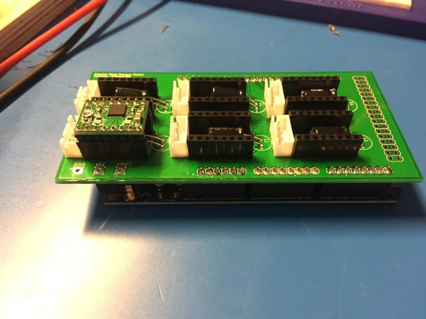
As for the electronics the plan is rather simple. There is a main 12V exponent provide, that tail deliver up to 3A of current, which powers the motors. A tone-down module is victimized to safely power the Arduino and a customised shield for the Arduino was designed that houses every last of the stepper motor drivers. The drivers make controlling the motors a lot easier. Driving a stepper motor requires a circumstantial control episode but by using motor drivers we only need to beget a high pulse for apiece step the motor shall call on. Additionally, some jst connectors were added to the shield to attain connecting the motors easier. The shield for the Arduino was firtsly built on a piece of perfboard and after devising sure that everything works as it was supposed to that got factory-made by jlc pcb.
Here's the before and after of the prototype and the factory-made pcb. 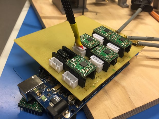
Pace 6: Software & Serial Interface
The Q-Bot is separate into two parts. Along the one hand there is the hardware that gets obsessed by the Arduino, on the other hand there is a piece of software that calculates the resolution path for the cube supported the current shin. The firmware running on the Arduino was written aside myself but ready to keep this guide on unawares I will not go into any inside information nearly it here. If you wish to take a look at it and play around with IT, the link to my git repository will be provided at the end of this papers. The software that calculates the solution runs on a windows machine and was written past a fellow worker of mine, again links to his source code can equal found at the remainder of this ible. The two parts communicate using a simple serial interface. It calculates the solution based on Kociemba's two form algorithm. The resolution software sends a command consisting of two bytes to the solver and waits for it to return an 'ACK'. This way the solver hind end live tested and debugged using a simple serial monitor. The sodding teaching set hind end be found below.
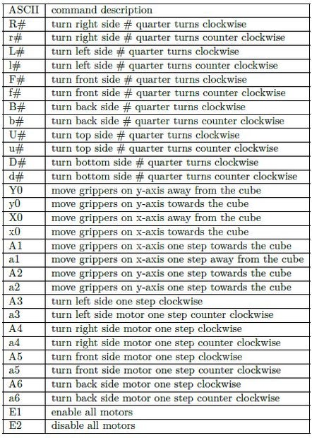
The commands to routine each causative for one footfall are a workaround for a problem where some of the steppers would willy-nilly perform small jumps upon power up. To cover for this the motors can be adjusted to their initial position prior to the solving process.
Step 7: Conclusion
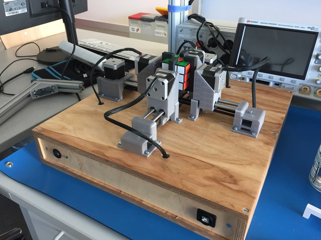
After eighter months of developing, swearing, hitting the keyboard and dancing the Q-bot was finally at a luff where is successfully solved its first Rubik's Cube. The scramble of the third power had to exist inserted manually into the control software, but everything worked well.
I added a mount for a webcam few weeks later and my college orientated the computer software to say the dice automatically from the images embezzled. However, this is not tested recovered yet and lul needs some improvements.
If this instructable sparked your interest assume't waver and start building your very personal version of the Q-bot. It might seem discouraging at get-go, but it is very much worth the effort and if I could do it so can you.
Resources:
Source Code of the Microcode:
https://github.com/Axodarap/QBot_firmware
Source Code of the control software
https://github.com/waldhube16/Qbot_SW
Constitute the First to Share
Recommendations
Source: https://www.instructables.com/Q-Bot-the-Open-Source-Rubiks-Cube-Solver/
Posted by: sotoorgoods.blogspot.com
0 Response to "Q-Bot - the Open Source Rubik's Cube Solver : 7 Steps (with Pictures) - sotoorgoods"
Post a Comment